2026-05-30 13:00:07
Many simulator-style games have their own dedicated controllers, from racing sims with pedals, steering wheels, and shifters to flight sims which have their own joysticks and sometimes entire cockpits. But for how prevalent riding horses is in a wide array of video games from Red Dead Redemption to Zelda to The Witcher we’re not sure we’ve ever seen a controller built specifically for riding virtual horses, at least not until [Squalius] built this horse riding controller.
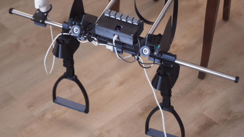
[Squalius] has been working through a few prototypes of his OpenRidingController and has a fairly complete riding setup now, complete with reins and stirrups for controlling one’s in-game companions. The reins are attached to infrared distance sensors which can send analog signals to the game for controlling steering, and are attached to each other through an elastic band to provide a more realistic feeling when both are pulled to ask the horse to stop. The stirrups can be pulled to tell the horse to move at various speeds, and although a horse doesn’t need to be commanded to jump in real life, this controller provides a method for jumping an in-game horse as well.
Although we’ve mentioned a few games famous for using horses already, [Squalius] also added a handheld joystick to enable his controller to be used in less-conventional games like Minecraft where the player can use a mod to add a horse, and has also used his controller to play DOOM as well. As its name suggests it’s also open source and the code for it is all available on the project’s GitHub page. It’s a type of controller we didn’t realize we were missing until now, and perhaps we would have expected to see one before something like a controller meant for a virtual trombone.
Thanks to [Keith] for the tip!
2026-05-30 10:00:44
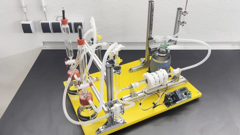
Plastics, oil, petrol– the modern world is entirely dependent on hydrocarbons. The good sources are slowly running low and supply is increasingly complicated by geopolitical factors we really don’t want to get into, but hey! It’s just hydrogen and carbon, right like it says in the name. How hard could it be to roll your own at home. Well, if you’ve got a lab like [Marb]’s Lab on YouTube, it might just be doable, as he demonstrates in his latest video.
The Fischer-Tropsch reaction was discovered back in 1925 in Germany by a couple of gents named Fischer and Tropsch. In the unpleasantness that followed later, Germany made good use of their process on an industrial scale, since they had ample coal and no oil on hand. Coal-rich South Africa has also made us of it, particularly during the Apartheid-era trade restrictions. Every so often the idea of industrializing the process comes up in the USA, but there’s still enough oil there it doesn’t make sense economically.
Those nations all have something in common: they’re all coal-rich countries, and that makes sense because coal is easily converted to carbon monoxide and hydrogen– a combo known as syngas– and it just so happens that those are the feedstock for this reaction. The actual chemistry going on inside is quite complex, but conceptually it is pretty simple: hydrogen and carbon monoxide mix over a hot metal catalyst, and combine to form various hydrocarbons.
In [Marb]’s glassware-based demonstration, the catalyst is Cobalt (III) Oxide on silica gel– a lovely, cancer-causing substance that must be prepared for each use, as it lasts but 24 hours before further oxidization ruins it. That’s in spite of purging the system with argon– a necessary step if one does not wish to explode. The yield isn’t amazing, and [Marb] isn’t sure exactly what mix of hydrocarbons he has created– although they smell like gasoline and burn like the dickens, so mission accomplished.
This might seem like the furthest thing from green, but if you use solar power to run the process and something like woodgas– which is syngas by any other name– as a feed-stock, then you’ve got a carbon neutral energy storage medium.
Thanks to [Markus Bindhammer] for the tip!
2026-05-30 07:00:44
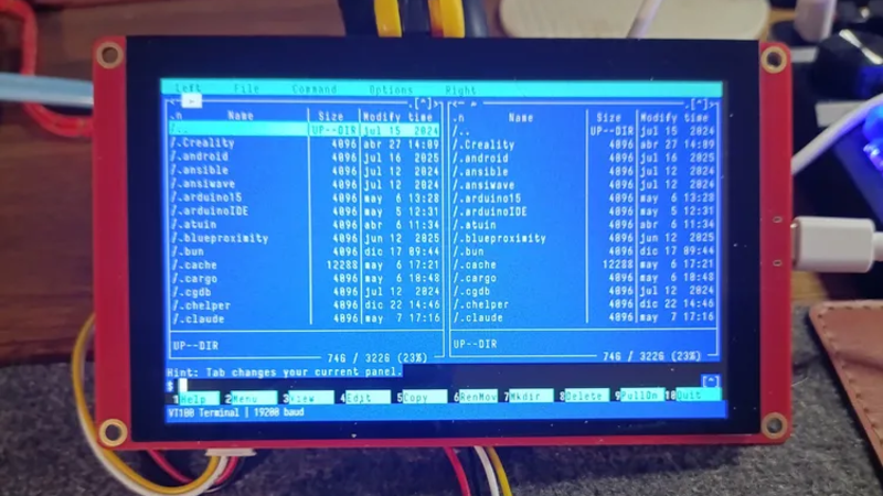
If you’re of a certain vintage, you have probably looked at some of the microcomputers on the market these days and thought “that would have been a decent workstation back in the day!”. We certianly have, and so did [Roberto Alsina]. Rather than allow himself to contemplate his age and threfore rapidly approaching mortailty, [Roberto] wrote a useful operating system called ESP-Osito for the Cheap Yellow Display, which he refers to as “the cheapest computer”. He’s not wrong, and it’s certainly a better use of time than an existential crisis.
He explains some of his reasoning behind the project in an accompanying blog post, but on the project page he compares it to a Palm Pilot– it’s on quick, apps load quick, and the API is simple enough for easy app creation in a few hundred lines of C, unlike certain pocket computers we won’t name. Sure, there’s no multitasking, but when apps jump from SD card to run in memory in microseconds, who cares? Saving the current state of the app back to SD means the experience is virtually identical from a user perspective anyway.
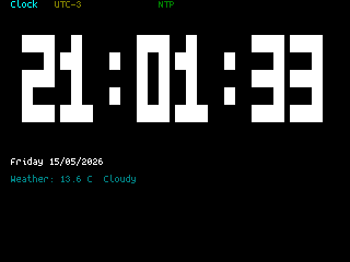
As this is a one-man show for now, the app store won’t quite rival your smart phone– but there’s everything you’d expect on the 90s-era computer this has the horsepower of: a serial terminal, a text editor, a file explorer, a calculator, a clock, but also some things that aren’t so retro. The clock app gives weather info via futuristic wireless networking, the reader app takes Markdown text, and the chat app connects to an LLM somewhere instead of your friends on IRC. The blackberry keyboard option gives it a feel of a slightly different vintage. You can also play snake, because no computer is complete without games. The OS and all its applications are released under the MIT license on GitHub, and [Roberto] is actively looking for collaborators.
If you doubt the workstation comparison at the start of this article, this CYD runs Macintosh System 3 via a 68k emulator. That’s got old-school cred, but there’s something great about having retro constraints with modern code on modern hardware. In that way, ESP-Osito is similar to the 3D graphics engine behind this Wipeout clone.
2026-05-30 04:00:48

Ever since wealthy European landowners started displaying vast, unused swaths of turfgrass as status symbols, regular folk have been chasing that perfectly mown and tended lawn for similar reasons. In the modern era, most mowers used to maintain these spaces use a spinning blade attached to a motor of some sort, but this can be dangerous especially on rocky fields like [Greenhill Forge] needs to mow. For these fields it’s best to use a different type of mower, and he’s built one from scratch.
This type of mower is called a flail mower, which has hinged, sharpened hammers attached to a central rotating drum. Since the flails have less rotational speed at the ends, they are less dangerous if they strike solid objects like rocks. To build one, he first builds the central drum and flails, then the enclosure to mount it to his tractor, and then a drivetrain to attach it to the tractor’s PTO. Since everything is getting built in [Greenhill Forge]’s metalworking shop, many of the parts needed to be fabricated from scratch, which involved several jigs for the plasma cutter as well as forging some steel to make some of the thicker parts.
Although not many of us have fully-stocked metalworking shops like this, it shows that almost anything can be built with the right tools. A forge is actually fairly accessible for those looking to start smithing; we’ve seen them built from little more than an off-the-shelf unmodified microwave or from a propane torch and some cookware.
2026-05-30 02:30:40
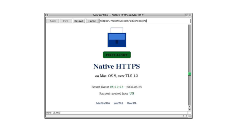
When using older computers there comes a point at which modern software drops support, as for example is happening with builds for Windows XP. Every now and then though, along comes something that bucks the trend. Enter [mplsllc] with Macsurf, a port of the Netsurf browser for classic MacOS 9 on PowerPC. Bring your nineties beige box back online!
The first generation of PowerPC Macs occupy an odd position, being faster and more capable than their predecessors while not sharing the ability to run MacOS X like their G3 descendants. Macsurf has the promise of bringing them into the 2020s, but if you’re expecting the equivalent of Google Chrome you might be disappointed.
Netsurf is a browser that started life on RiscOS, the original ARM OS from the Acorn Archimedes. It’s lightweight and portable, it’s an active project, it has a good rendering engine that does up to date HTML and CSS, it offers native TLS, and it has JavaScript built in. It’s ideal for a 1990s PowerPC, but with the caveat that sites expecting the very latest browsers might struggle. Sadly we don’t have a ’90s Mac to hand so we can’t try this port, but we’re used to it on other lower-power machines so we thing it’ll be a great asset to the platform.
We last looked at Netsurf when we had a look at RiscOS, if you are interested.
2026-05-30 01:00:48

Elliot Williams is out where the deer and the antelope play for the next week, so it’s up to Tom Nardi and Al Williams to wrangle this episode of the Hackaday Podcast. They’ll start off by reading some listener messages before talking about the slow extinction of time broadcasts, Linux on cheap smartphones, microcontroller VPNs, and the computers of Spacelab.
You’ll also hear about using a video game’s “Photo Mode” to capture 3D imagery, strange red lights in deep space, and ASCII fish that you don’t need to feed. The episode wraps up with a discussion of WWII spy tech and the revelation that modern smartphones and powerful magnets don’t always mix.
Check out the links if you want to follow along, and as always, tell us what you think about this episode in the comments!
Direct download in DRM-free MP3.