2026-07-15 06:00:00
上一篇我们用 Kueue + NVIDIA 原生 DRA 跑通了 GPU 整卡配额:Job 先进入队列,Kueue 判断配额够不够,够了再放行给调度器。
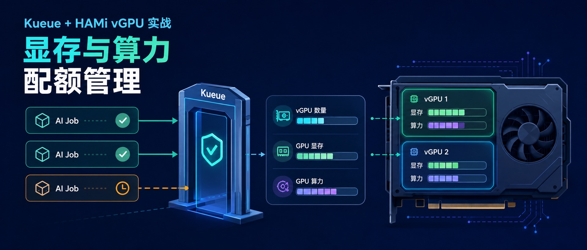
但整卡只是第一步。真实的 GPU 集群里,一张 GPU 往往不会只给一个 Pod 用,HAMi 可以继续按显存和算力切成 vGPU。问题也跟着来了:切完之后,队列系统还能不能知道每个任务用了多少?能不能做到两个任务放行、第三个因为显存或算力配额不够继续排队?
这篇就围绕这个问题跑一遍:HAMi 把 GPU 切给 Pod,Kueue 在 Job 准入阶段先把 vGPU、显存和算力配额算清楚。重点不是“能不能切卡”,而是“切完之后还能不能管起来”。
环境基本沿用上一篇 Kueue + NVIDIA DRA 的测试环境。区别只有两点:
本文的命令和输出来自这套环境:
|
|
K8s 集群、GPU Operator、Kueue 的安装过程前几篇已经写过,这里不再重复。需要确认的一点是:后面由 HAMi 接管 GPU 切分,所以 GPU Operator 安装时要关闭 NVIDIA DevicePlugin:
|
|
节点上能看到 T4 即可:
|
|
HAMi DRA Webhook 需要 TLS 证书,因此需要提前安装 cert-manager 用于自动签发。
|
|
给节点打上 gpu=on 标签。未标记的节点不会被 HAMi 接管。
|
|
安装 HAMi,并通过 --set dra.enabled=true 开启 DRA 模式:
|
|
注意:DRA 模式与传统模式不兼容,请勿同时启用。
gpu=on 主要给 HAMi 做节点选择。后面 ResourceFlavor 用的 nvidia.com/gpu.product=Tesla-T4,则是 GPU Operator / GFD 自动打到节点上的标签。
另外,如果 GPU 驱动是主机预装,非 GPU Operator 安装,则安装时需额外指定:
|
|
HAMi 正常启动后,hami-system 下会看到三个核心组件:
|
|
底层发布出来的 GPU 资源也要确认一下:
|
|
ResourceSlice 里记录了这张 T4 的显存和算力容量:
|
|
需要注意的是 allowMultipleAllocations: true:同一张物理 GPU 可以被多个 ResourceClaim 消费,只要显存和算力容量还够,切卡才有空间。
对 HAMi 不熟悉的同学可以先看看这篇文章:Kubernetes GPU 虚拟化实战:HAMi DRA 模式完整指南
HAMi DRA 现在有两种使用方式:
| 模式 | 用户怎么写 | 谁创建底层设备申请 | 更适合什么场景 |
|---|---|---|---|
| DRA 原生模式 | 手写 ResourceClaim / ResourceClaimTemplate
|
用户 | 新业务直接接 DRA API |
| 兼容模式 | 写 nvidia.com/gpu/gpumem/gpucores
|
HAMi webhook | 存量 HAMi 业务迁移 |
我这次实测下来,Kueue 接 HAMi 原生 DRA 时,更容易先做到按 claim / 设备数量做准入;但要把 gpumem/gpucores 也纳入 Kueue 配额,兼容模式反而更顺:业务侧仍然写 nvidia.com/gpu/gpumem/gpucores,Kueue 通过 ResourceTransformation 把它们折算成队列里的总量配额资源。
所以这篇走兼容模式,业务 YAML 继续写熟悉的 HAMi 资源:
|
|
含义是:
| 资源 | 含义 |
|---|---|
nvidia.com/gpu: 1 |
申请 1 个 vGPU 设备实例 |
nvidia.com/gpumem: 4096 |
每个 vGPU 申请 4096Mi 显存 |
nvidia.com/gpucores: 50 |
每个 vGPU 申请 50% 算力 |
HAMi webhook 会拦截这个 Pod,把上面的资源申请转换成底层设备申请。调度时,kube-scheduler 看到的是 HAMi 发布出来的 GPU 设备,以及对应的显存、算力容量。
这里用一个最小例子把链路跑通。先验证 HAMi 能不能切出 4Gi / 50 cores;确认没有问题以后,再接入 Kueue,观察它会不会在准入阶段扣配额。
为了把变量降到最低,先不接 Kueue,直接提交一个 Pod:
|
|
Pod 创建后,HAMi webhook 会把原始资源申请改成 ResourceClaim:
|
|
对应的 ResourceClaim 如下:
|
|
容器里看到的显存也变成了 4096Mi:
|
|
到这里可以确认 HAMi vGPU 已经生效:业务 YAML 仍然写 nvidia.com/gpu/gpumem/gpucores,容器里实际只看到被切分后的 4096Mi 显存。
HAMi 验证通过后,就可以把 Kueue 接进来了。接入前需要先把配额口径捋清楚:HAMi 的 nvidia.com/gpumem 和 nvidia.com/gpucores 是“每个 vGPU”的资源。比如这次 Demo 里有两个相同规格的 Job,每个 Job 都申请:
|
|
那么队列整体在配额上应该按总量扣减:
|
|
Kueue 管队列配额时应该看总量,所以要在 Kueue 配置里加 ResourceTransformation。这次用的是 Kueue 0.18.1:
|
|
这几行最关键的是两个动作:
nvidia.com/gpumem
nvidia.com/total-gpumem
gpucores 同理,转成 nvidia.com/total-gpucores
multiplyBy: nvidia.com/gpu 表示先乘以 vGPU 个数,再进入 Kueue 配额修改 kueue-manager-config 后重启 Kueue:
|
|
这次只用一个队列,把资源扣减先看清楚。
场景:
|
|
Kueue 配置:
|
|
这里的显存配额写 8192,和业务侧的 nvidia.com/gpumem: 4096 保持同一个口径:单位都是 Mi。单个 Job 会被 Kueue 统计成 nvidia.com/total-gpumem: 4096,两个相同 Job 加起来就是 8192。
提交一个 4Gi / 50 cores 的 Job:
|
|
结果:
|
|
看 Workload 的准入结果:
|
|
这个结果就是 Kueue 介入后的关键变化:Pod 还没进入调度阶段,Workload 已经先按 vGPU 个数、总显存、总算力扣了一次配额。
HAMi 生成的 ResourceClaim 也可以对上:
|
|
容器里也能看到 4096Mi 显存上限:
|
|
继续提交两个相同规格的 Job:
|
|
队列总配额是:
|
|
因此第 2 个 Job 可以准入,第 3 个 Job 会继续留在队列里:
|
|
ClusterQueue 的用量已经打满:
|
|
Pending Workload 里能看到原因:
|
|
这也是我更关心的点:不是等 Pod 到调度阶段才 Pending,而是在 Job 准入阶段就把超配额任务留在队列里。
第一个坑是小数 GPU。不要写 nvidia.com/gpu: "0.5"。
Kubernetes 扩展资源必须是整数,而且 GPU 这类不可超卖资源要写在 limits 里。正确写法是:
|
|
半张卡 这种说法在 HAMi 里应该理解成:1 个 vGPU 实例 + 部分显存 + 部分算力,不是 0.5 个 nvidia.com/gpu。
只把 nvidia.com/gpu 放进 Kueue,只能限制 vGPU 个数,管不了显存和算力。
要把 HAMi 的切分资源纳入 Kueue 配额,需要做这两个转换:
|
|
ClusterQueue 里也要同时配置这三个资源:
|
|
这一篇跑完后,Kueue 系列基本就从 CPU 队列一路串到了 GPU 整卡和 HAMi vGPU。真落到 GPU 集群里,光能切卡还不够,准入和配额也一样重要: GPU 虚拟化解决的是"怎么切",Kueue 解决的是"谁先用、谁能用多少"。两者结合起来,GPU 集群才真正具备了多租户管理能力。
2026-07-02 06:00:00

前面两篇:Kubernetes 官方出品:一个 Controller 搞定 Job 排队和资源配额 和 终于搞懂 Kueue:5 个核心对象一次讲透 把 Kueue 的基本玩法和核心对象走了一遍,不过 Demo 都跑在 CPU 上。
真到 GPU 集群里,大家更关心的是另一个问题:
Kueue 能不能管理 DRA 模式下的 GPU?
这一篇就把它跑通。NVIDIA DRA Driver 负责把整卡 GPU 发布成 DeviceClass / ResourceSlice,Kueue 在 Job 准入阶段读取 DRA 设备申请,判断这个 Job 能不能进入队列。
对 DRA 不熟悉的同学,可以先看这篇:DRA P1:DRA 能解决什么问题?从部署到使用的完整体验
环境准备分几段走:先创建 K8s 集群,再用 GPU Operator 把 GPU Driver / Container Runtime 准备好,最后装 Kueue 和 NVIDIA DRA Driver。
集群使用 KubeClipper 创建。KubeClipper 1.6.0 默认支持 Kubernetes 1.36.1、containerd 2.2.4,和本文环境一致,详细步骤可以参考:KubeClipper 1.6.0 发布:kcctl 优化与 K8s 1.36 支持。
快速创建单节点集群的命令如下:
|
|
集群起来后确认版本:
|
|
GPU Driver、NVIDIA Container Toolkit 等基础组件使用 GPU Operator 安装。完整说明可以参考之前这篇:GPU 环境搭建指南:使用 GPU Operator 加速 Kubernetes GPU 环境搭建。
本文后面会安装 NVIDIA DRA Driver,所以安装 GPU Operator 时需要关闭 DevicePlugin:
|
|
--set devicePlugin.enabled=false:关闭 DevicePlugin,避免与后续安装的 DRA Driver 冲突。
安装完成后,确认 GPU Operator 组件正常运行:
|
|
再确认节点能看到 GPU:
|
|
Kueue 使用 0.18.1,安装方式和前两篇一样:
|
|
如果测试环境访问 registry.k8s.io 不稳定,也可以用 GitHub Release 里的 chart 包:
|
|
最后安装 NVIDIA DRA Driver 25.12.0:
|
|
安装完成后,先看 DRA Driver 组件:
|
|
再看 DeviceClass:
|
|
整卡调度用的是 gpu.nvidia.com。对应的 ResourceSlice 里能看到节点上的 T4:
|
|
后面的 Job 会直接引用 gpu.nvidia.com 这个 DeviceClass,实际可分配设备则来自这些 ResourceSlice。
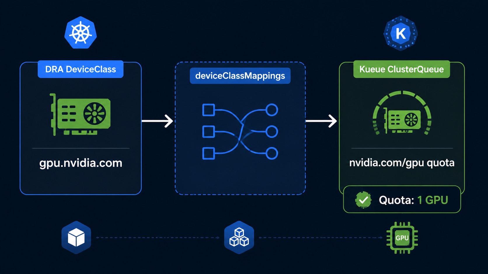
DRA 和 Kueue 使用的资源名称并不是同一个。ResourceClaimTemplate 里写的是 deviceClassName: gpu.nvidia.com,而 ClusterQueue 里扣配额用的是资源名,所以这里需要做一次映射:
|
|
这段配置的意思是:只要 Workload 通过 ResourceClaimTemplate 申请 gpu.nvidia.com 这个 DeviceClass,Kueue 就把它折算成 nvidia.com/gpu 这个逻辑资源来扣配额。
修改 Kueue manager config 后,需要重启 kueue-controller-manager 让新配置生效。
这次只用一个队列,GPU 配额只给 1 张 T4。这样后面再提交第二个 Job 时,Pending 状态会看得很清楚。
|
|
注意这里的 coveredResources 里包含 nvidia.com/gpu。这是映射后的逻辑资源名,不是 Pod 里直接写的扩展资源。
使用 DRA 之后,Job 不再写 resources.limits.nvidia.com/gpu: 1,而是引用一个独立的 ResourceClaimTemplate。
这里 Kueue 做的事情很直接:读取 Workload 引用的 ResourceClaimTemplate,识别里面的 deviceClassName 和 count,再通过 deviceClassMappings 折算成 ClusterQueue 里的配额资源。
本文不展开 extended resource 路径,避免把两种 DRA 接入方式混在一起。
先创建 ResourceClaimTemplate:
|
|
这里有两个细节容易混:
deviceClassName 是 gpu.nvidia.com,不是 nvidia.com/gpu
ExactCount + count: 1 表示申请 1 张整卡再提交 Kueue 管理的 Job:
|
|
Job 被 Kueue 准入后,会从 Suspended 变成 Running:
|
|
ResourceClaim 已经分配:
|
|
容器里能看到 T4:
|
|
直接看 Workload 的准入结果:
|
|
这说明 deviceClassMappings 已经生效:用户写的是 ResourceClaimTemplate,Kueue 扣的是 nvidia.com/gpu 这个逻辑配额。
再看看 ClusterQueue,可以发现 GPU 配额已经被扣掉了:
|
|
队列里只有 1 张 GPU 配额。如果再提交一个同样申请 single-gpu 的 Job:
|
|
|
|
再看 Workload 状态,就能发现为什么第二个 Job 一直起不来:
|
|
ResourceClaimTemplate 里写的是:
|
|
ClusterQueue 里写的是:
|
|
两者靠 Kueue 配置里的 deviceClassMappings 关联起来。少了这段映射,Workload 会被标成 Inadmissible,原因类似:
|
|
这两个名字最容易看混:
single-gpu:前面单独创建的 ResourceClaimTemplate,定义“我要 1 张 gpu.nvidia.com 整卡”。gpu-claim:Pod 里的本地 claim 名字,后面容器通过它来使用 GPU。Pod 里这段不是重新定义一个模板,而是引用已经存在的 single-gpu 模板:
|
|
容器里再通过同一个 gpu-claim 关联到这次申请到的设备:
|
|
所以完整关系是:ResourceClaimTemplate(single-gpu) -> Pod resourceClaims(gpu-claim) -> container resources.claims(gpu-claim)。
这里要注意一点:Kueue 只是负责“准入”,真正把 GPU 分配给 Pod 的还是 kube-scheduler 和 DRA Driver。
所以生产环境里建议同时关注 ResourceClaim 状态和 Pod 状态。如果希望 Workload 在 Pod 长时间起不来时释放 Kueue 配额,可以结合 waitForPodsReady 做保护。
到这里可以看到,Kueue 并没有直接参与 GPU 分配,而是站在 Job 准入这一层,通过 deviceClassMappings 把 DRA 的设备申请转换成队列里的配额资源。这样既保留了 DRA 的设备模型,也让 GPU 可以继续纳入 Kueue 的统一配额管理。
| 组件 | 负责什么 |
|---|---|
| NVIDIA DRA Driver | 把 GPU 作为 gpu.nvidia.com DeviceClass / ResourceSlice 发布出来 |
| Kueue | 通过 deviceClassMappings 把 DRA 设备折算成 nvidia.com/gpu 配额 |
| kube-scheduler | 在 Pod 调度阶段完成 ResourceClaim 的实际设备分配 |
下一篇继续往前走一步,把 HAMi 引入进来:一张 GPU 被切成多份 vGPU 之后,Kueue 是否还能继续管理显存和算力配额。
2026-07-01 06:00:00
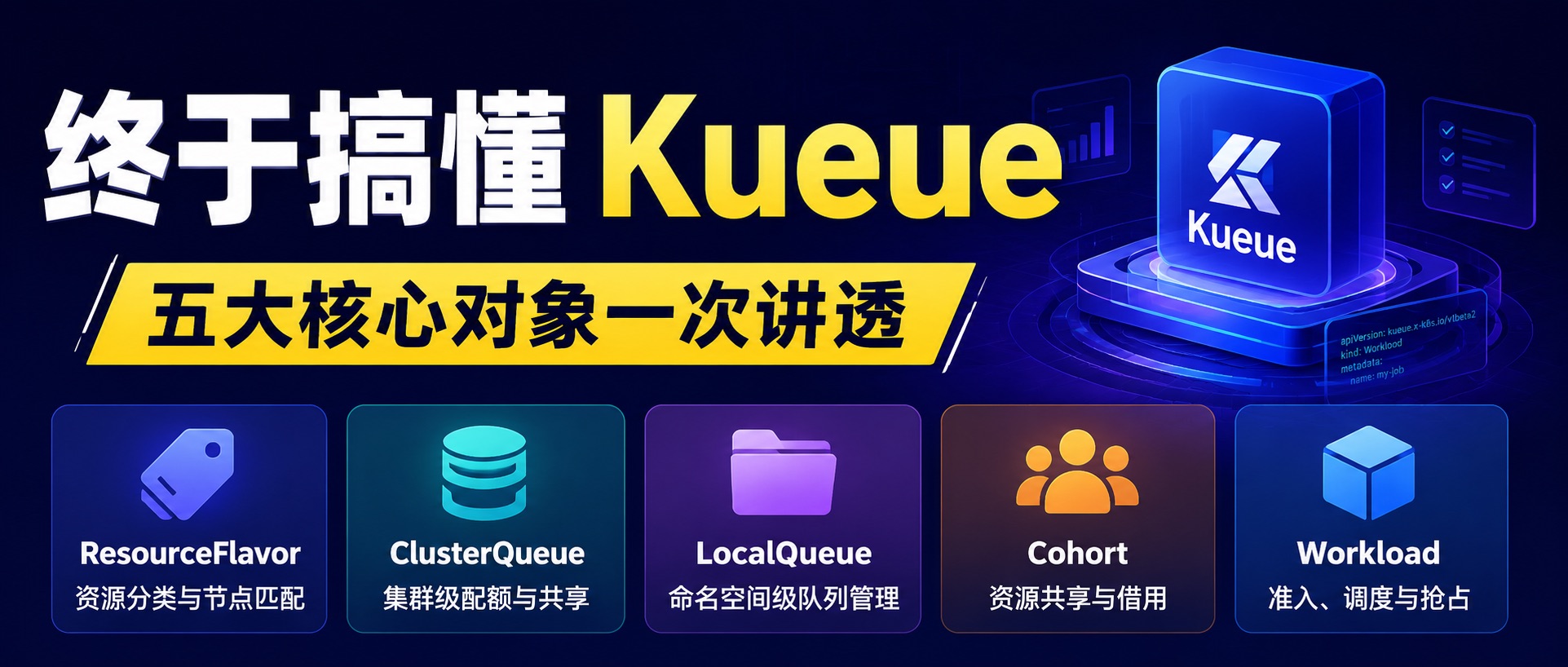
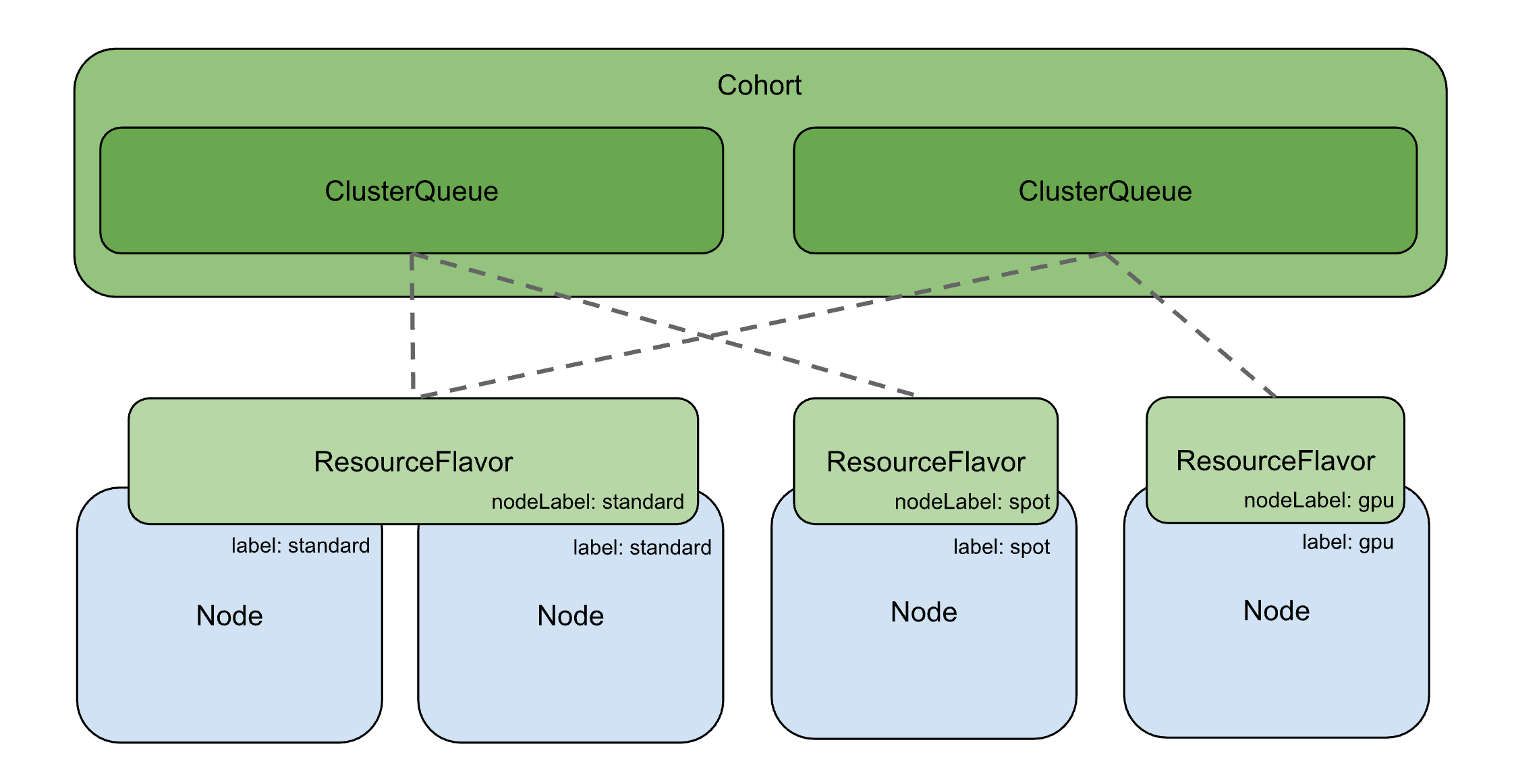
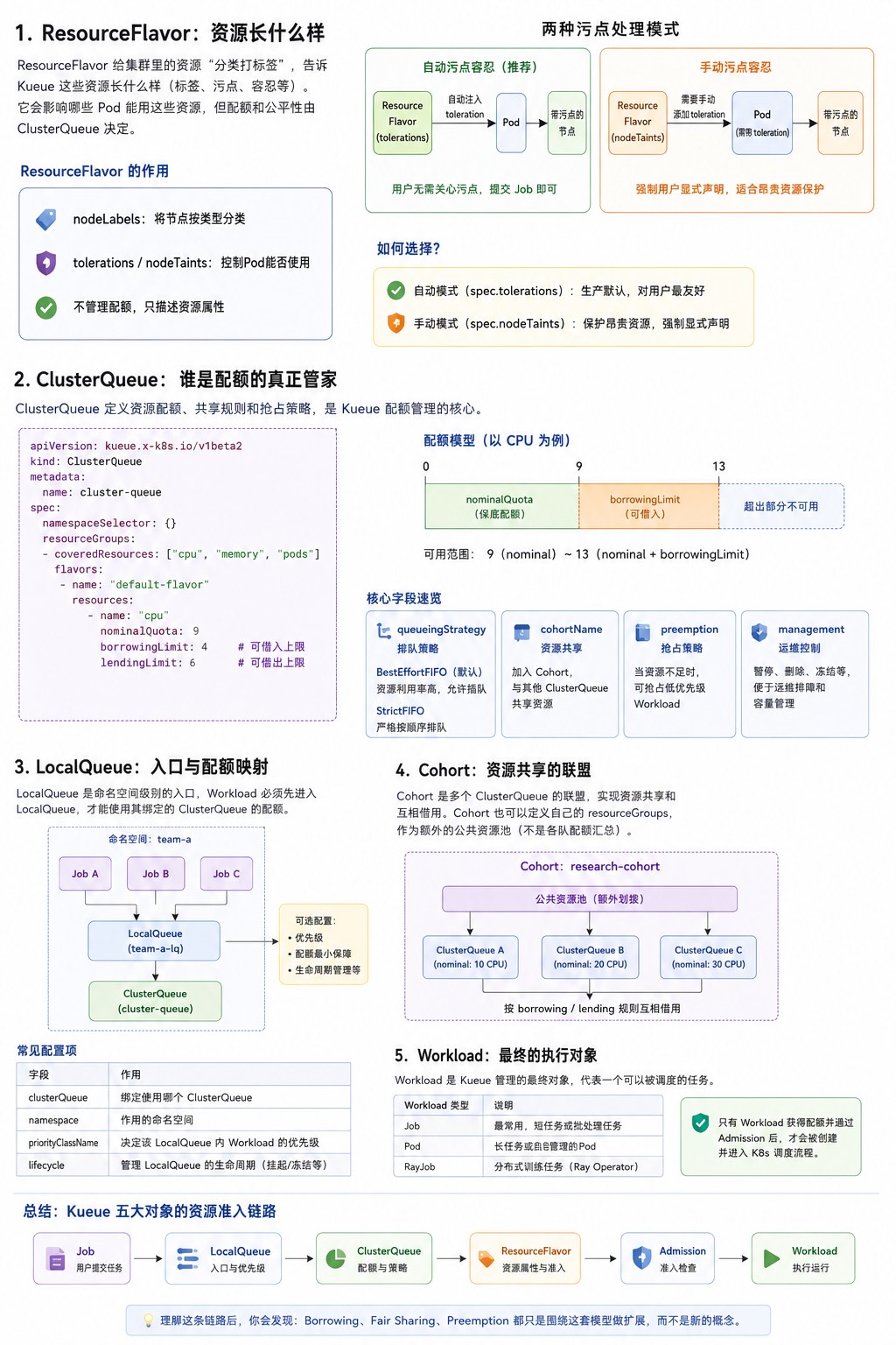
很多人刚接触 Kueue 时最大的困惑,不是 YAML 怎么写,而是看着一堆 CRD:ResourceFlavor、ClusterQueue、LocalQueue、Cohort、Workload,不知道它们之间到底是什么关系。本文不会逐个照着 API 文档介绍字段,而是把这五个对象放到同一条资源准入链路中,一次讲清楚它们各自负责什么、为什么要存在,以及它们之间如何协作。
上一篇文章中分析了 Kueue 的完整工作流:
涉及到多个核心对象,下面逐个拆开讲。
Kueue 要管资源,第一步得知道集群里有哪些"种类"的资源。集群里的 CPU、GPU 通常不是同构的:
ResourceFlavor 就是干这个的——给资源分个类,贴个标签,后面 ClusterQueue 按这个分类来管配额。
Kueue 在 Admission 阶段,会根据 ClusterQueue 中配置的 Flavor 顺序、Quota 是否满足、Flavor 是否匹配 Pod 等因素,选择一个可用的 ResourceFlavor。
如果集群资源是同构的,或者不需要为不同资源规格分别管理配额,那直接创建一个不包含任何标签或污点的空 ResourceFlavor 即可:
|
|
这类 ResourceFlavor 不承担节点筛选或污点控制的职责,仅作为统一的资源抽象存在,方便后续扩展不同资源类型。
|
|
新增参数:
spec.nodeLabels :通过 label 关联到对应的节点。具体实现上则是通过将 flavor 中 nodeLabels 部分自动注入到 Pod Spec 中的 nodeSelector,从而达到只将 Pod 调度到该 flavor 关联的节点上。这类 Flavor 实现了根据 label 将节点进行分类,算是名副其实。管理员先给节点打上对应 label 即可实现分类:
|
|
但也只是简单做了分类,不是该 Flavor 中的 Job 也能手动调度到这些 GPU 节点。比较推荐的做法是给节点再打上污点,这样就不是随便能调度上去了:
|
|
节点打上污点后,Flavor 中的 Job 也不能调度了。Kueue 提供了两种模式来解决这个问题:
|
|
新增参数:
spec.tolerations :声明该 flavor 关联节点上的污点容忍信息。Kueue 准入时自动注入到 Pod 的 .spec.template.spec.tolerations,确保 Pod 能容忍节点污点从而正常调度。
|
|
新增参数:
spec.nodeTaints :在 flavor 上定义准入门槛。Kueue 不会自动注入容忍度,Pod 必须自己带对应 toleration 才能通过准入、拿到配额。用户提交 Job 时必须自己带上 toleration,否则 Kueue 不批配额:
|
|
注意 :
spec.nodeTaints通常应与节点上的真实污点保持一致。否则可能出现 Pod 过了 Kueue 准入、拿到配额,但 K8s 调度器发现节点有真污点而 Pod 没对应 toleration,最终调度失败——白白占了配额。本质就是把调度层面的拦截提前到 Kueue 准入层面。
自动模式(spec.tolerations) |
手动模式(spec.nodeTaints) |
|
|---|---|---|
| 谁给 Pod 加 toleration | Kueue 自动注入 | 用户自己写 |
| 用户需要关心节点污点吗 | 不需要,提交 Job 就行 | 必须自己写 toleration |
| 用在哪 | 生产默认,对用户最友好 | 保护昂贵资源,强制用户显式声明 |
选型建议:优先用自动模式;只有当你需要强制用户显式声明才能使用某种昂贵资源时,才用手动模式。
一句话记住:ResourceFlavor 定义资源的属性(标签、污点、容忍等),真正决定资源配额和公平性的仍然是 ClusterQueue。
如果 ResourceFlavor 是给资源分类,那真正决定谁能用、用多少的是谁?答案就是 ClusterQueue。它才是 Kueue 配额管理的核心,定义了使用上限和公平共享规则。
一个基础的 ClusterQueue 示例如下:
|
|
字段解析:
spec.namespaceSelector :指定该 ClusterQueue 可以在哪些 namespace 被使用。当前 ClusterQueue 可以被任意 Namespace 使用。resourceGroups :资源组,定义 ClusterQueue 的资源额度,可以有多个,每个组都是独立的。
coveredResources :管哪些资源,同一个 group 里面的资源必须在同一个 flavor 里面分配。flavors :可以有多个,分配是按顺序尝试。
name :使用名称引用前面创建的 ResourceFlavor。resources :在这个 flavor 下,每种资源的配额上限。
nominalQuota :保底配额,表示该 ClusterQueue 的名义配额,优先保障自身使用;未使用的部分可以按照 borrowing/lending 规则被其他 Queue 借用。borrowingLimit :你最多能从 Cohort 里借入多少,所以你最多能用 nominalQuota + borrowingLimit。lendingLimit :你最多允许别人从你这借走多少(当你空闲时),需要时可通过预抢占收回。以 cpu 为例,基于上面三个配额字段,你可以使用的范围是 nominalQuota ~ (nominalQuota + borrowingLimit)。
在基础配置之上,ClusterQueue 还支持以下进阶字段,按用途分组:
|
|
BestEffortFIFO(默认) :前面的 Job 拿不到配额,后面的能插队先跑,资源利用率高。StrictFIFO :前面的 Job 拿不到配额,后面的必须等,适合有顺序依赖的 Pipeline。
|
|
cohortName :关联到一个 Cohort,同一个 Cohort 里的 ClusterQueue 可以互相共享资源。当 ClusterQueue 或其 Cohort 中没有足够的配额时,新进入的 Workload 可以触发预抢占,挤掉低优先级的 Workload。涉及两个配置项:
预抢占策略
|
|
withinClusterQueue :同队列内,当待处理 Workload 不适合配额时,是否可抢占同队列中的活动 Workload。Never(默认)不抢占;LowerPriority 仅抢占低优先级;LowerOrNewerEqualPriority 抢占低优先级或同优先级的。reclaimWithinCohort :是否可抢占 Cohort 中使用了超过其名义配额的 Workload。Never(默认)不抢占;LowerPriority 仅抢占低优先级;Any 可抢占任意优先级。borrowWithinCohort :当需要借用配额时是否触发抢占。Never(默认)不触发;LowerPriority 仅抢占 Cohort 中低优先级的 Workload(需同时启用 reclaimWithinCohort)。注意:只能配置经典抢占,不能与 Fair Sharing 一同使用。优先抢占还是借用
当 ClusterQueue 有多个 flavor 时,Kueue 按顺序尝试。当当前 flavor 配额用完时,你可以影响 Kueue 的行为:
whenCanBorrow :能从 Cohort 借的时候。MayStopSearch(默认):借了就停,不再试下一个;TryNextFlavor:不借,先试下一个 flavor。whenCanPreempt :能抢占低优先级 Job 的时候。TryNextFlavor(默认):先试下一个 flavor;MayStopSearch:不试了,直接抢占。
|
|
控制队列的运行状态,ClusterQueue 和 LocalQueue 都支持。
None(默认) :正常运行,新 Job 正常准入,已运行的不受影响。Hold :停止新的准入,已准入的不受影响,适合维护、配额调整等临时场景。HoldAndDrain :停止新的准入 + 触发已准入工作负载的驱逐,适合紧急情况需要立刻清场。维护完恢复为 None 或直接删掉这个字段即可。这是运维操作,不是常态配置。
|
|
一个包含所有字段的完整 ClusterQueue:
|
|
一句话记住:ClusterQueue 才是真正管配额和公平性的地方。 第一次看会和 LocalQueue 搞混,其实记住一句就够了——ClusterQueue 管资源,LocalQueue 管用户。
ClusterQueue 是集群级别的,但用户不能直接往里塞 Job。中间还需要一层 LocalQueue——它是一个命名空间对象,指向一个 ClusterQueue,作为用户提交 Job 的入口。
|
|
注意:
kubectl get queues是kubectl get localqueues的别名,更方便日常使用。
| 维度 | LocalQueue | ClusterQueue |
|---|---|---|
| 作用域 | 命名空间 | 集群 |
| 谁创建 | 团队自己 | 批处理管理员 |
| 职责 | 将同一租户的工作负载分组,指向一个 ClusterQueue | 管理资源池的配额和公平共享规则 |
| 一对一? | 多个 LocalQueue 可以指向同一个 ClusterQueue | — |
|
|
一句话记住:LocalQueue 就是 Namespace 访问 ClusterQueue 的入口。 它不管配额,只管"我这个 namespace 的 Job 往哪个 ClusterQueue 送"。
如果每个 ClusterQueue 只能用自己的保底配额,那 team-a 闲着 3 核、team-b 想多跑 1 核也借不到,资源就浪费了。Cohort 就是解决这个的——可以理解成一个"资源共享联盟",加进同一个 Cohort 的 ClusterQueue 可以互相借配额。
第一次看 Cohort 我也没太理解。后来发现,它本身还能定义 resourceGroups(共享配额池),这些资源是管理员额外划拨给整个联盟的公共池,而不是把各个 ClusterQueue 的 nominalQuota 自动汇总得到的。
|
|
上面的配置意味着:
nominalQuota(即使值为 0)Cohort 可以组织成树形结构(CohortTree),适合大型组织:
|
|
|
|
同一个 CohortTree 中的 ClusterQueue 可以使用其中的资源,遵循为 Cohort 和 ClusterQueue 指定的借用和借出限制。
一句话记住:Cohort 让多个 ClusterQueue 可以互相借资源。
前面四个都是"配置",那 Kueue 真正调度、准入的对象是什么?是 Workload——一个要运行至完成的应用,由一个或多个 Pod 组成。Kueue 的 Admission、Quota Accounting、Preemption 全是围绕它展开的。
通常你不需要手动创建 Workload,Kueue 会为每个 Job 自动创建。但理解它的结构有助于排查问题。
|
|
Workload 的优先级影响准入顺序,有两种设置方式:
batch/v1.Job,Kueue 根据 Job 的 Pod 模板的 Pod 优先级设置 Workload 的优先级
|
|
使用方式:在 Job 的 label 中指定:
|
|
Kueue 将 Workload 的总资源使用量计算为每个 podSet 资源请求的总和:
podSet 的资源使用量 = Pod 规格的资源请求 × count
Kueue 会根据 Limit Ranges 和 Runtime Class Overhead 调整资源使用量。
一句话记住:Workload 才是 Kueue 真正调度和准入的对象,前面四个对象都是给它配规则的。
理论讲完了,下面用一个 demo 把五大核心对象串起来,验证配额管控和 Cohort 借用能力。环境是一个单节点 K8s 集群(8 核 CPU)+ Kueue v0.18.1。
|
|
|
|
|
|
|
|
|
|
30 秒后 Job A 跑完,验证 Kueue 自动注入了 toleration 和 nodeSelector:
|
|
team-b 保底只有 2 核,要 3 核需要从 team-a 借 1 核空闲配额(此时 Job A 还在跑,用了 3 核,team-a 空闲 1 核)。 此时提交 JobB:
|
|
借用过程:team-a 保底 4 核用了 3 核,空闲 1 核 → team-b 保底 2 核不够(要 3 核)→ 从 team-a 借了 1 核 → 准入成功。
30 秒后 Job B 跑完,team-b 的 3 核配额归还。等 Job A 也跑完后,整个 Cohort 就空了:team-a 保底 4 核全空闲,team-b 保底 2 核全空闲,总共 6 核可借。
Job A、Job B 都已跑完,配额全部归还。现在 team-b 最多能用保底 2 + 借 3 = 5 核(team-a 空闲 4 核,足够借)。
|
|
结果:
|
|
|
|
结果:
|
|
| Job | 团队 | 请求 CPU | 保底 | 借用 | 结果 |
|---|---|---|---|---|---|
| Job A | team-a | 3 核 | 4 核 | 0 | ✅ 准入 |
| Job B | team-b | 3 核 | 2 核 | 借 1 核 | ✅ 准入 |
| Job D | team-b | 5 核 | 2 核 | 借 3 核 | ✅ 准入(到 borrowingLimit 上限) |
| Job E | team-b | 1 核 | 已满 | 无法借 | ❌ Pending |
5 个核心对象在这里全部串联起来了。
Kueue 的核心,其实不是“调度算法”,而是围绕 Workload 的准入与资源分配模型。
五个对象分别扮演了不同角色,但可以用一句话快速串起来:
第一次接触 Kueue 时,很容易把这些对象看成彼此独立的 CRD,但实际上它们共同组成了一条完整的资源准入链路:
|
|
理解了这条链路,再去看 Borrowing、Fair Sharing、Preemption 等高级能力,就会发现它们都只是围绕这套模型做扩展,而不是新的概念。
2026-06-25 06:00:00
多个团队共用一个 Kubernetes 集群,A 团队提交了一批训练任务,几十张 GPU 很快就被占满;B 团队新提交的 Job 只能一直 Pending。 因为,而是 Kubernetes 原生采用"先到先得"的调度方式,没有 Job 队列,也没有多租户配额管理。
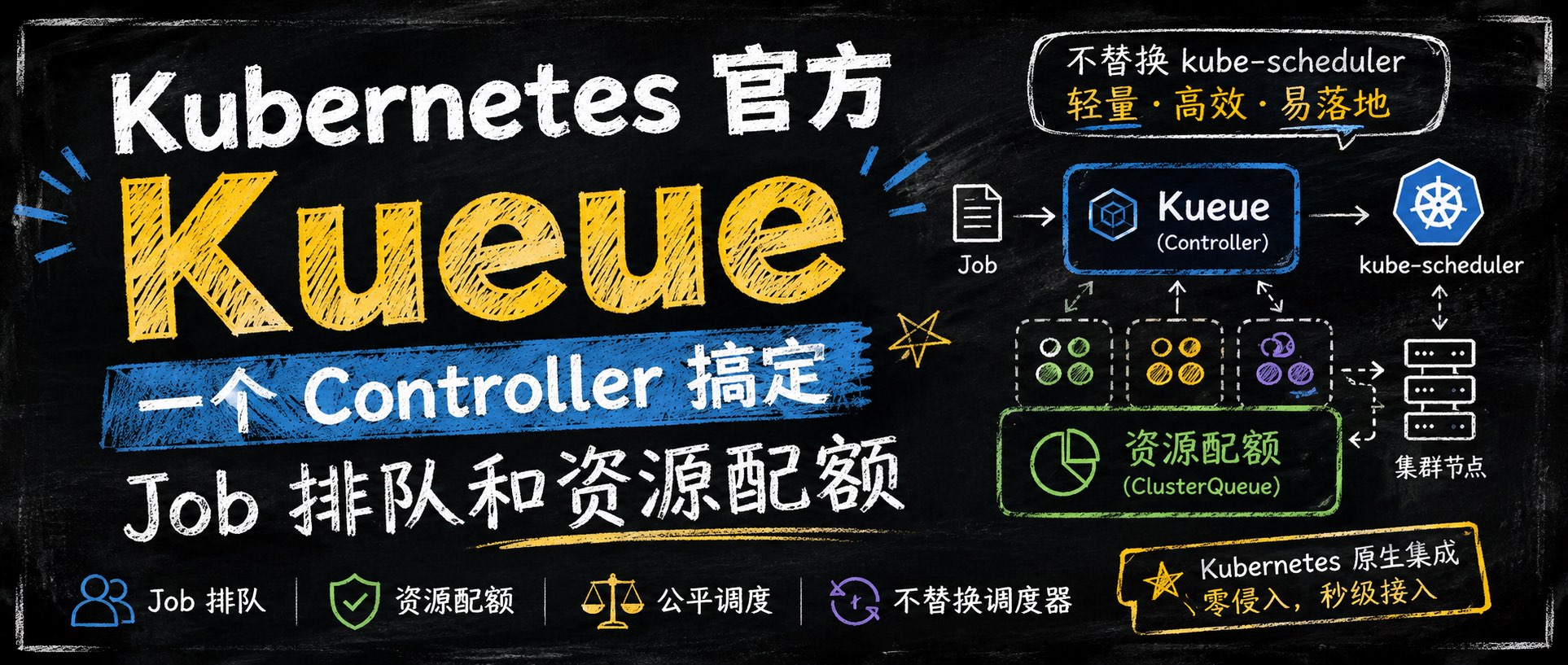
Kueue 正是 Kubernetes 官方为此提供的解决方案。它不替换 kube-scheduler,只负责 Job 的排队和准入,在此基础上实现资源配额管理和公平调度。
Kueue 是 Kubernetes SIGs 维护的官方 Job 级队列管理系统,负责决定 Job 何时准入(Admit)、何时被驱逐(Preempt),核心目标是管理资源配额和多租户公平调度。
和 Volcano 最大的区别:Kueue 不替换 kube-scheduler,它只管"排队和准入",调度还是交给原生调度器。
|
|
多租户配额管理:通过 ClusterQueue 为不同团队划分资源配额
公平调度:基于 Dominant Resource Shares(DRS)的公平共享算法,防止资源被单一团队长期独占
队列排队:Job 提交后按优先级排队,配额不足时挂起等待
Cohort 借调:同一 Cohort 内的 ClusterQueue 可以借用彼此空闲配额,用完归还
弹性配额:支持 nominalQuota(保底)+ borrowingLimit(借用上限)+ lendingLimit(出借上限)三层额度控制
标准兼容:原生支持 K8s Job / JobSet / PyTorchJob / TFJob / RayJob 等,无需改 Job YAML
或者说 Kueue 解决了什么原生 K8s 解决不了的问题?
原生 Kubernetes 的资源管理是"先到先得",没有队列的概念:
| 场景 | 原生 Kubernetes | Kueue | 优势 |
|---|---|---|---|
| 配额管理 | ResourceQuota 粗粒度控制 | ClusterQueue 细粒度配额(按 GPU 型号/节点池划分) | 精确到资源类型和 Flavor |
| 多租户公平 | 先到先得,无法保障公平 | Fair Sharing 基于 DRS 的公平分配 | 防止资源独占 |
| Job 排队 | Pending 后只能等 | 支持优先级队列、FIFO 策略 | 按优先级有序调度 |
| 跨团队借调 | 不支持 | Cohort 机制,空闲配额自动借出、按需归还 | 提高集群利用率 |
举一个典型场景:公司有两个 AI 团队共享一个 GPU 集群,各有 50% 的 A100 配额。团队 A 没任务时,团队 B 可以借用全部 GPU;团队 A 提交任务后,Kueue 会通过 preemption 让团队 B 释放借用的资源,回到公平状态。
原生 K8s 做不到这一点。
| 维度 | Kueue | Volcano |
|---|---|---|
| 定位 | 队列 + 配额管理(轻量) | 批处理调度平台(重量) |
| 架构 | 不替换调度器,旁路管理 | 自定义调度器,替换 kube-scheduler |
| 归属 | Kubernetes SIGs 官方 | CNCF(华为发起) |
| 部署复杂度 | 一个 Controller | Scheduler + Controller + Admission 三个组件 |
| Gang Scheduling | 通过 All-or-Nothing with Ready Pods(超时机制) | 原生 Gang Scheduling |
| Job API | 标准 K8s Job(自动创建 Workload) | 自定义 VolcanoJob(vcjob) |
更多参考:Kueue 官方文档、Volcano 系列文章
在部署之前,先理解 Kueue 的 5 个核心对象:
|
|
ResourceFlavor:Flavor,代表不同类型的资源(如 A100 vs T4、Spot vs On-Demand),可以绑定 nodeLabels / taints
ClusterQueue:集群级队列,定义资源配额(nominalQuota / borrowingLimit / lendingLimit),是配额管理的核心
LocalQueue:命名空间级队列,用户直接和它打交道,指向一个 ClusterQueue
Cohort:ClusterQueue 的组,同组内可以互相借调空闲配额
Workload:Kueue 的调度单元,Kueue 会为每个 Job 自动创建对应的 Workload,用户一般不需要手动创建
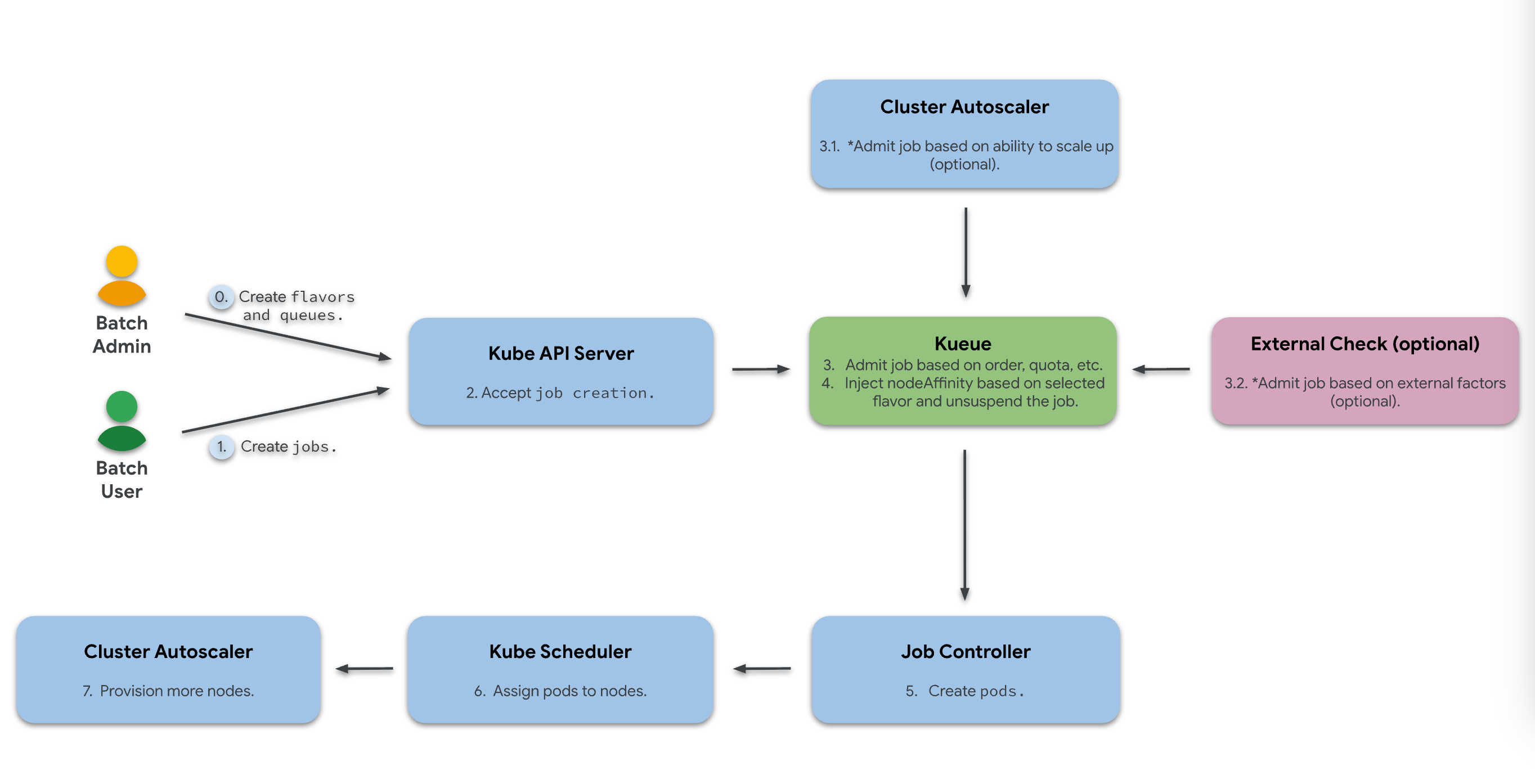
一个 Job 从提交到运行,经过 Kueue 的完整流程:
|
|
关键点:Kueue 只负责"准入"决策,Pod 真正调度到哪个节点还是 kube-scheduler 决定。
Kueue 部署非常轻量,只需要一个 Controller。
Kueue 要求 Kubernetes 1.29+,本文使用 Kubernetes v1.36.1 部署最新的 Kueue v0.18.1。
官方提供了两种安装方式,推荐 Helm:
|
|
|
|
无法访问
registry.k8s.io可以从 GitHub 下载 chart 包安装:
1 2 3 4helm install kueue https://github.com/kubernetes-sigs/kueue/releases/download/v0.18.1/kueue-0.18.1.tgz \ --namespace kueue-system \ --create-namespace \ --wait --timeout 300s
|
|
|
|
|
|
一个 Pod 就搞定了,这就是 Kueue 轻量的地方。
接下来我们跑一个最小化 Demo:创建 ResourceFlavor → ClusterQueue → LocalQueue → 提交 Job,完整走一遍 Kueue 的工作流程。
Kueue 使用三种资源来管理作业排队:
|
|
|
|
|
|
|
|
队列创建成功,当前没有 Workload。
注意看,这里用的就是标准的 K8s Job,只需要加一个 label 就能接入 Kueue:
|
|
|
|
|
|
|
|
可以看到 Kueue 自动为 Job 创建了对应的 Workload,Workload 状态为 Admitted(已准入),3 个 Pod 正常运行。
|
|
|
|
Job 完成后,Workload 也会被标记为 Finished:
|
|
|
|
到这里,我们完整走了一遍 Kueue 的工作流程:创建队列 → 提交 Job → Kueue 自动准入 → Pod 运行 → 任务完成。
整个过程中,我们用的是标准的 K8s Job,唯一的变化就是加了一个 kueue.x-k8s.io/queue-name 标签。这就是 Kueue “不替换调度器、旁路管理"设计哲学的体现。
Kueue 是 Kubernetes SIGs 官方出品的 Job 队列与配额管理系统,它的核心设计哲学是”只管排队和准入,不动调度器",这让它非常轻量且对现有集群侵入性极小。
本文介绍了 Kueue 的背景、核心概念和部署方式,并通过一个最小化 Demo 走完了"创建队列 → 提交 Job → 自动准入 → 任务完成"的完整流程。
下一篇我们将深入解析 Kueue 的五大核心对象(ResourceFlavor / ClusterQueue / LocalQueue / Cohort / Workload),搞清楚它们各自的职责和配置细节。
2026-06-17 06:00:00
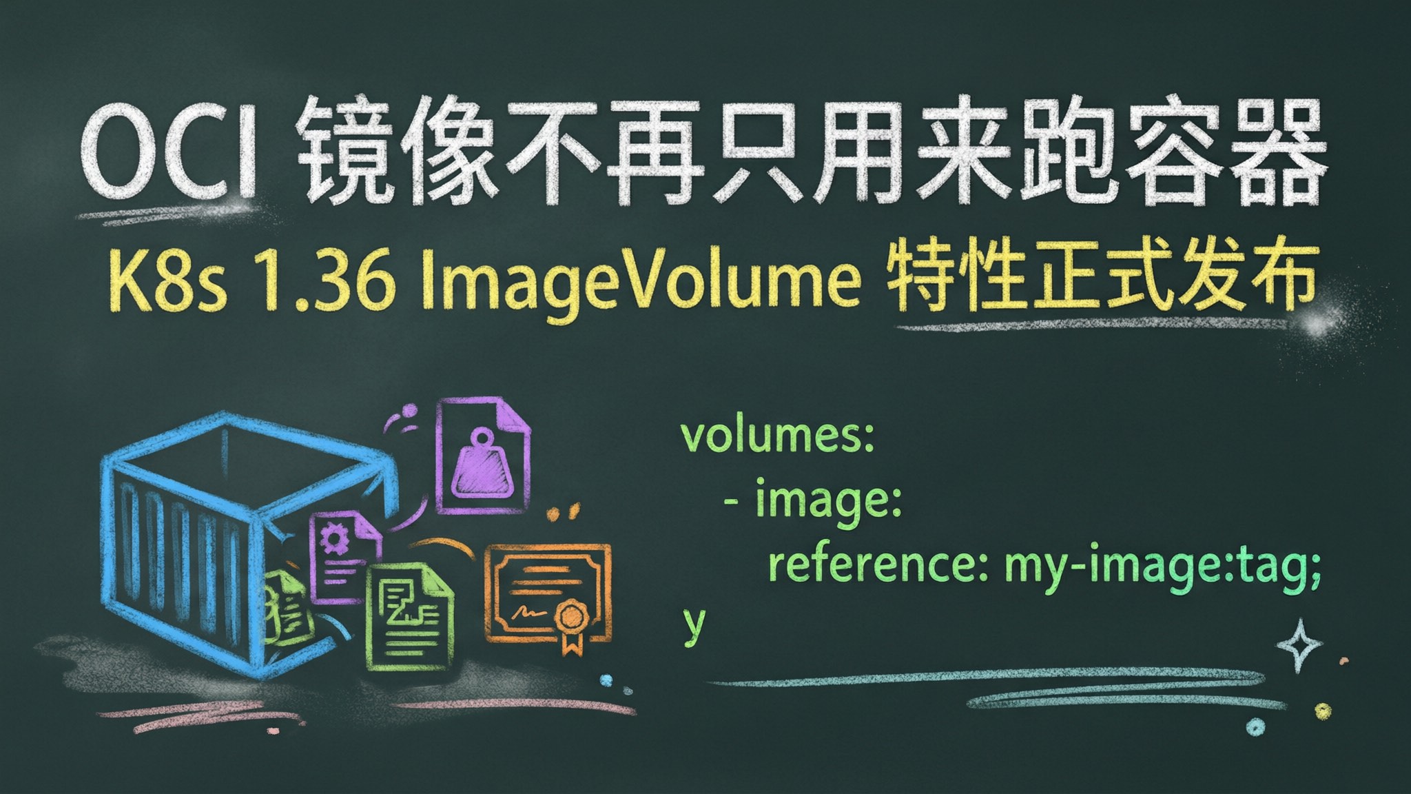
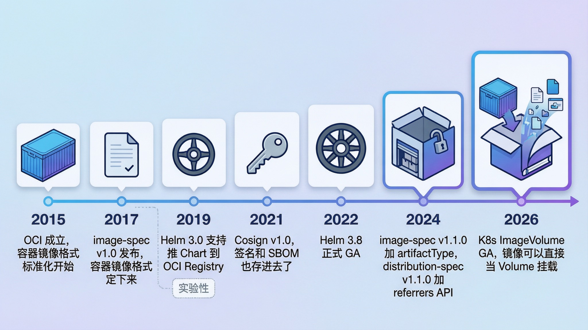
OCI 规范建立的目的就是将容器镜像格式标准化,正如其名,OCI 镜像在之前一直用来跑容器,但现在它还能干更多事。
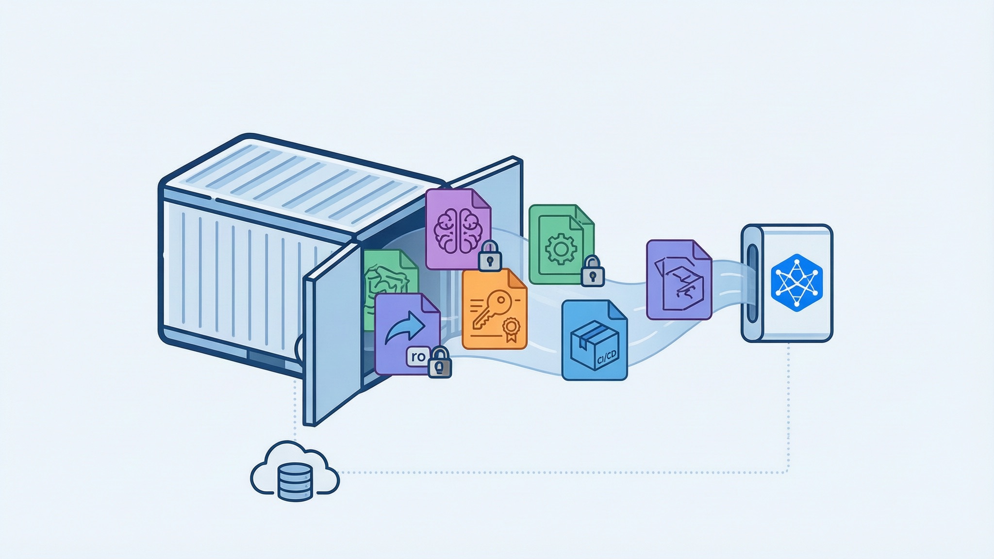
Kubernetes v1.36 里 ImageVolume 特性正式 GA 了,该特性允许我们把 OCI 镜像直接作为 Volume 挂载到 Pod 里。现在 OCI 镜像在 K8s 里不再只能跑容器了,模型权重、配置文件、安全签名、CI/CD 工件,只要是只读数据,都可以打包成 OCI 镜像供 Pod 挂载使用。
这个特性从 v1.31 以 Alpha 引入,经过 v1.33、v1.35 的 Beta 阶段,终于在 v1.36 正式 GA。GA 之后不用再手动开 Feature Gate,containerd 也原生支持了,开箱即用。
OCI(Open Container Initiative)是 2015 年在 Linux 基金会支持下成立的开放项目,Docker、CoreOS(后来被 Red Hat 收购)和容器行业的主要厂商一起,围绕容器格式和运行时制定了开放标准。Docker 捐出了自己的镜像格式作为基础,社区在此基础上逐步形成了 Runtime、Image 和 Distribution 三大规范。
2017 年 image-spec v1.0 发布,容器镜像的格式算是定下来了。在 OCI 标准下,运行一个容器的过程就是:从 Registry 下载 OCI 镜像 → 解压到 OCI Bundle → OCI Runtime 运行这个 Bundle。整个流程标准化之后,不同 Runtime、不同 Registry 之间可以互操作,不用强行绑定 Docker。
Docker 也把 libcontainer 的实现移动到 runC 捐给了 OCI,社区有了第一个 OCI Runtime 的参考实现。
虽然 OCI 标准最初完全是围绕容器设计的,镜像格式里的 mediaType、config 结构都是为「跑容器」量身定做的。
但是如果我不想跑容器,只想把一堆文件打包分发呢?人们很快发现,OCI Registry 的分层存储和分发机制天然适合分发更多东西。
OCI 镜像的本质是什么?就是一堆只读的层(layer),加上一个 manifest 描述这些层的组织方式,再通过 Registry 的 API 完成分发。同时 OCI Registry 提供了一整套“可寻址、可校验、可去重、可控访问”的分发原语,然后这个模型并不绑定「容器」。
所以社区很自然地想到:能不能把 OCI Registry 当成一个通用的内容分发平台来用?
实际上社区很早就开始在 OCI Registry 里存非镜像内容了,但早期的做法都是 hack——把非镜像内容伪装成容器镜像塞进去,Registry 其实并不知道这些东西不是用来跑的:
OCI Artifacts 就是这么来的,把各种产物存进 OCI Registry、当成通用内容仓库来分发。
这些用法推动了 OCI 规范本身的演进。2024 年,image-spec v1.1.0 正式加入了 artifactType 字段,允许 Manifest 声明「我不是容器镜像,我是一个签名 / 一个 Helm Chart / 一个模型权重」。OCI 对非镜像内容的支持从社区 hack 变成了规范的一部分,OCI Registry 正式成为了一个通用的内容仓库。
现在 OCI Registry 已经变成了一个通用的内容仓库,但问题来了:Helm、Cosign、ORAS 这些工具都在往里塞东西,但到了 Kubernetes 这边,OCI 镜像还是只能拿来跑容器,缺少一个原生的消费方式。
ImageVolume 就是来补上这一块的。它允许在 Pod 中将 OCI 镜像直接作为 Volume 挂载,让 OCI Artifacts 在 K8s 里也能被原生消费,不再只是跑容器。就像这样:
|
|
不过有一点要注意,ImageVolume 挂载是只读的,如果需要在运行时修改挂载的文件,还是得用 PVC。后面会详细讨论这个限制。
ImageVolume 让 OCI Artifacts 在 K8s 里有了第一个原生的消费方式。不过这个能力并不是一步到位的,从 Alpha 到 GA 走了近两年。
ImageVolume 这个特性来源于 KEP-4639,由 SIG Node 和 SIG Storage 共同推动。从 v1.31 Alpha 到 v1.36 GA 走了近两年,具体时间线如下:
| 阶段 | K8s 版本 | 发布时间 | Feature Gate 默认值 | 说明 |
|---|---|---|---|---|
| Alpha | v1.31 | 2024-08 | false |
需要手动开启 Feature Gate |
| Beta(默认关) | v1.33 | 2025-04 | false |
Beta 代码合入但仍默认关闭 |
| Beta(默认关) | v1.34 | 2025-08 | false |
移除 noexec 限制,仍默认关闭 |
| Beta(默认开) | v1.35 | 2025-12 | true |
首次默认启用 |
| GA | v1.36 | 2026-04 |
true(锁定) |
Feature Gate 锁定,v1.39 移除 |
Containerd v2.1.0 才正式支持 ImageVolume,而且没有回移到 v2.0.x 分支,所以用 containerd 的话必须升级到 v2.1.0+。
接下来过一遍每个阶段的变化。
Alpha 阶段 ImageVolume 不支持 subPath,也就是说你只能挂载镜像的整个文件系统,没法只挂载其中的某个子目录。
Beta 阶段(v1.33)解除了这个限制,subPath 和 subPathExpr 都可以用了。对应的 CRI API 也新增了 image_sub_path 字段来支持这个功能。
现在你可以这样用:
|
|
很多时候一个镜像里会放多个目录,有了 subPath 就不用把整个镜像都挂进来了。
Alpha 阶段 ImageVolume 挂载时强制加了 noexec 选项,挂载进来的文件不能被执行。
这个限制在 Beta 阶段(2025-06,PR #5354)被移除了。社区讨论后觉得 noexec 限制过于严格,ImageVolume 的主要用途是分发只读数据,强制 noexec 没有必要,反而限制了某些合理的使用场景,比如挂载包含可执行工具的镜像。
不过 ImageVolume 仍然是只读挂载(ro),读写支持还得等后续的 KEP。
Beta 阶段新增了 3 个 Kubelet 指标,方便监控 ImageVolume 的使用情况。
kubelet_image_volume_requested_total — 请求的 ImageVolume 数量kubelet_image_volume_mounted_succeed_total — ImageVolume 挂载成功的数量kubelet_image_volume_mounted_errors_total — ImageVolume 挂载失败的数量GA 阶段这些指标提升到了 BETA 稳定性级别,可以在 Prometheus 里配告警了。
v1.36 GA 后,ImageVolume Feature Gate 被锁定为默认开启,没法关了。按照 K8s 的惯例,Feature Gate 会在 GA 后 3 个版本移除,也就是 v1.39 会彻底删掉这个 Gate。
所以现在的状态就是:
+featureGate=ImageVolume 注解也被移除了这个虽然不是 K8s 代码的变化,但可能是对使用者影响最大的变化。
Alpha 阶段,containerd 不支持 ImageVolume,想玩的话只能自己动手。参考我之前的文章 K8s V1.31 新特性:ImageVolume,
我当时手动 checkout 了 containerd 的 PR #10579,编译替换二进制文件。编译倒是不难,但是那个 PR 还有个 bug,kubelet 没有把 readOnly 参数透传到 CRI mounts 配置中,导致 containerd 校验 readOnly 失败一直报错。。。没办法,还得手动注释掉校验逻辑,整个流程折腾下来真的挺崩溃的。
现在 containerd v2.1.0 已经原生支持 ImageVolume,直接用就行,不需要任何 hack。
CRI-O 的话从 v1.31 就支持了,v1.34 还增加了 subPath 支持,一直走在前面。
整理一下:
| 变化项 | Alpha (v1.31) | Beta (v1.33-v1.35) | GA (v1.36) |
|---|---|---|---|
| subPath | ❌ 不支持 | ✅ 支持 | ✅ 支持 |
| noexec 限制 | 强制 noexec | 移除 | 无限制 |
| 监控指标 | 无 | Alpha 级别 | BETA 级别 |
| Feature Gate | 默认关,需手动开 | v1.33/34 默认关,v1.35 默认开 | 锁定开启 |
| containerd | 需手动编译 PR | v2.1.0 原生支持 | v2.1.0+ |
| CRI-O | v1.31 支持 | v1.34 支持 subPath | 同左 |
| 挂载模式 | 只读 | 只读 | 只读 |
变化聊完了,实际用起来是什么感觉呢。GA 之后用起来比 Alpha 阶段简单太多了,不用再折腾 Feature Gate 和手动编译 containerd 了。
就这么简单,不需要额外配置任何 Feature Gate。
本次验证环境是使用 KubeClipper 安装的 K8s 集群,版本如下:
使用方式和 Alpha 阶段基本一致。先构建一个包含模型文件的 OCI 镜像,用 FROM scratch 就行,不需要任何基础镜像。
为了后面演示 subPath,这里在镜像里放两个模型目录,再放一个配置文件:
|
|
目录结构如下:
|
|
Dockerfile 如下:
|
|
构建并推送到镜像仓库:
|
|
创建 Pod 挂载这个镜像:
|
|
应用到集群,等 Pod Running 后查看挂载内容:
|
|
镜像里的文件都挂载进来了,跟预期一致。
上面那个镜像里放了两个模型目录,如果 Pod 只需要 Qwen2-0.5B,不需要把整个镜像都挂进来,用 subPath 就行:
|
|
验证一下,挂载目录里只有 Qwen2-0.5B 的内容:
|
|
只挂载了 Qwen2-0.5B 目录,Llama2-7B 和 app.conf 都不在。如果 subPath 指定的路径在镜像中不存在,容器创建会直接报错:
|
|
ImageVolume 挂载是只读的,尝试写入会报 Read-only file system:
|
|
最后提几个实际使用中的注意事项。
ImageVolume 挂载是只读的,如果需要运行时修改文件还是得用 PVC,目前没有读写支持的 KEP。Pod 重建时 ImageVolume 会重新解析远端镜像,所以生产环境建议用 digest 而不是 tag 引用镜像,避免 Pod 重建后 tag 被覆盖导致拿到非预期版本。
镜像层共享能省磁盘,两个 ImageVolume 引用的镜像有相同层的话 containerd 只存一份,但大模型镜像多了也要注意节点磁盘压力。
OCI 从 2017 年 image-spec v1.0 发布到今天,走了一条挺清晰的路:先是容器镜像格式标准化,然后 OCI Registry 被社区 hack 成通用内容仓库,接着 image-spec v1.1.0 和 distribution-spec v1.1.0 把这种用法正式写入规范(artifactType + referrers API)。
OCI Artifacts 从社区变通变成了标准的一部分。ImageVolume GA 等于 Kubernetes 也跟上了,OCI Artifacts 在 K8s 里有了第一个原生的消费方式。
往后看,读写支持可能是下一个方向,目前只读挂载还是限制了些场景,社区已经有相关讨论。另外 ImageVolumeWithDigest 子特性在 v1.36 也 GA 了,Pod Status 里能直接看到挂载镜像的 digest,版本追溯方便不少。
2026-06-12 04:00:00

不知道你们有没有发现,进入 AI 时代之后,传统微服务那套 HPA 好像突然不好使了。
CPU 20%,内存 30%,监控面板一片岁月静好,但你的 AI 推理服务已经在排队了。HPA 看了一眼指标,嗯,一切正常,不用扩。
这不是 HPA 的 bug,是它背后那套「资源使用率等于负载压力」的逻辑,在 AI 推理场景下从根上就不成立。问题不在调参,在于观测信号本身就是失真的。
今天就来聊聊这件事的来龙去脉,以及目前我们认为最合理的解法,KEDA。
先说清楚 HPA 的底层逻辑。
HPA(Horizontal Pod Autoscaler)的设计假设是,资源使用率跟负载压力成正比。CPU 高了说明忙,内存高了说明扛不住,扩就完事了。对传统 Web 服务来说,这个假设基本成立,请求来了 CPU 就涨,请求走了 CPU 就降,很线性。
但 AI 推理服务把这个假设的每一个环节都打破了。以图片生成服务为例。
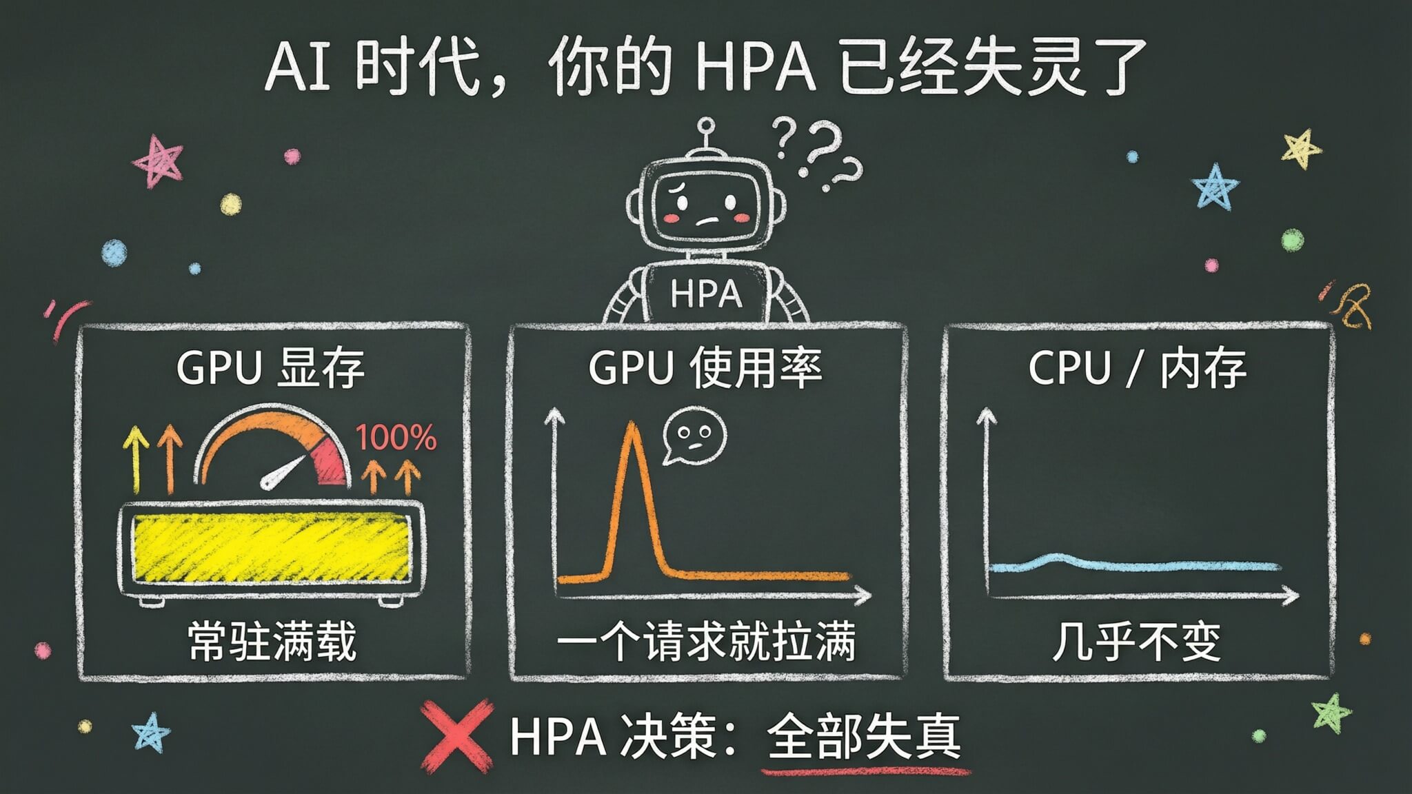
图片生成服务启动的时候,第一件事就是把模型权重加载到 GPU 显存里。比如 Stable Diffusion SDXL 这种级别的模型,光权重就要好几个 GB,加载完之后,这些显存就一直占着,不管你有没有请求,它都是满的。
所以你如果用 GPU 显存使用率做 HPA 指标,服务刚启动就已经「满」了。HPA 会觉得你一直需要扩容,即使压根没有任何请求在处理。
生成一张图片,一般要迭代几十上百步,整个过程可能就要几秒到几十秒。在这个过程中,GPU 使用率直接飙到 90% 甚至 100%。
问题在于,一个请求就能把 GPU 跑满。1 个请求和 10 个请求,在 GPU 使用率上看起来差不多,都是满载。 HPA 那套「采样窗口取平均值再做判断」的逻辑,放到这里完全没意义,因为不管采多少秒,看到的都是满载。
更离谱的是,你按 GPU 使用率做 HPA,一个请求过来就触发扩容,扩出来的 Pod 加载模型要 30 秒到 2 分钟,等它准备好,原来那个请求早就处理完了。
你可能会想,那 CPU 呢?内存呢?
推理服务的 CPU 主要做些预处理和调度,内存主要是模型权重的 CPU 侧缓存。0 个请求和 10 个请求的 CPU/内存使用,差别可能就是几个百分点。
所以,三个问题,三条路,全堵死了。HPA 最依赖的两个指标,在 AI 推理场景下,全部失真。
| 指标 | 传统 Web 服务 | AI 推理服务 |
|---|---|---|
| GPU 显存 | 随负载动态变化 | 模型加载后常驻满载 |
| GPU 计算使用率 | 与请求量正相关 | 一个请求就能拉满,无法反映积压程度 |
| CPU 使用率 | 与请求量正相关 | 仅做预处理,变化极小 |
| 内存使用率 | 与请求量正相关 | 主要是模型缓存,基本不变 |
| HPA 扩容效果 | 准确 | 失真 |
这就是为什么 HPA 在 AI 场景下不是扩错了,就是扩晚了,要么干脆就不扩。它的设计假设被 AI 服务或者 GPU 的工作模式彻底打碎了。
那怎么办?
HPA 之所以在 AI 场景下失灵,是因为它在看「机器忙不忙」。但 AI 推理的真正压力不在机器指标上,在「有多少活等着干」。
那「活」在哪?
形式不同本质一样,都是「有多少事还没干」。
对 AI 推理来说,最常见的载体是消息队列。图片生成、视频生成这些请求动辄几秒、几十秒甚至几分钟的,一般都会走异步处理。用户请求先进 MQ 排队,Worker 从队列里消费。队列里积压了多少消息,就是有多少待处理的推理请求。
这就是最真实的扩容信号。不根据指标看 GPU 忙不忙,直接看系统里有多少活没干完。
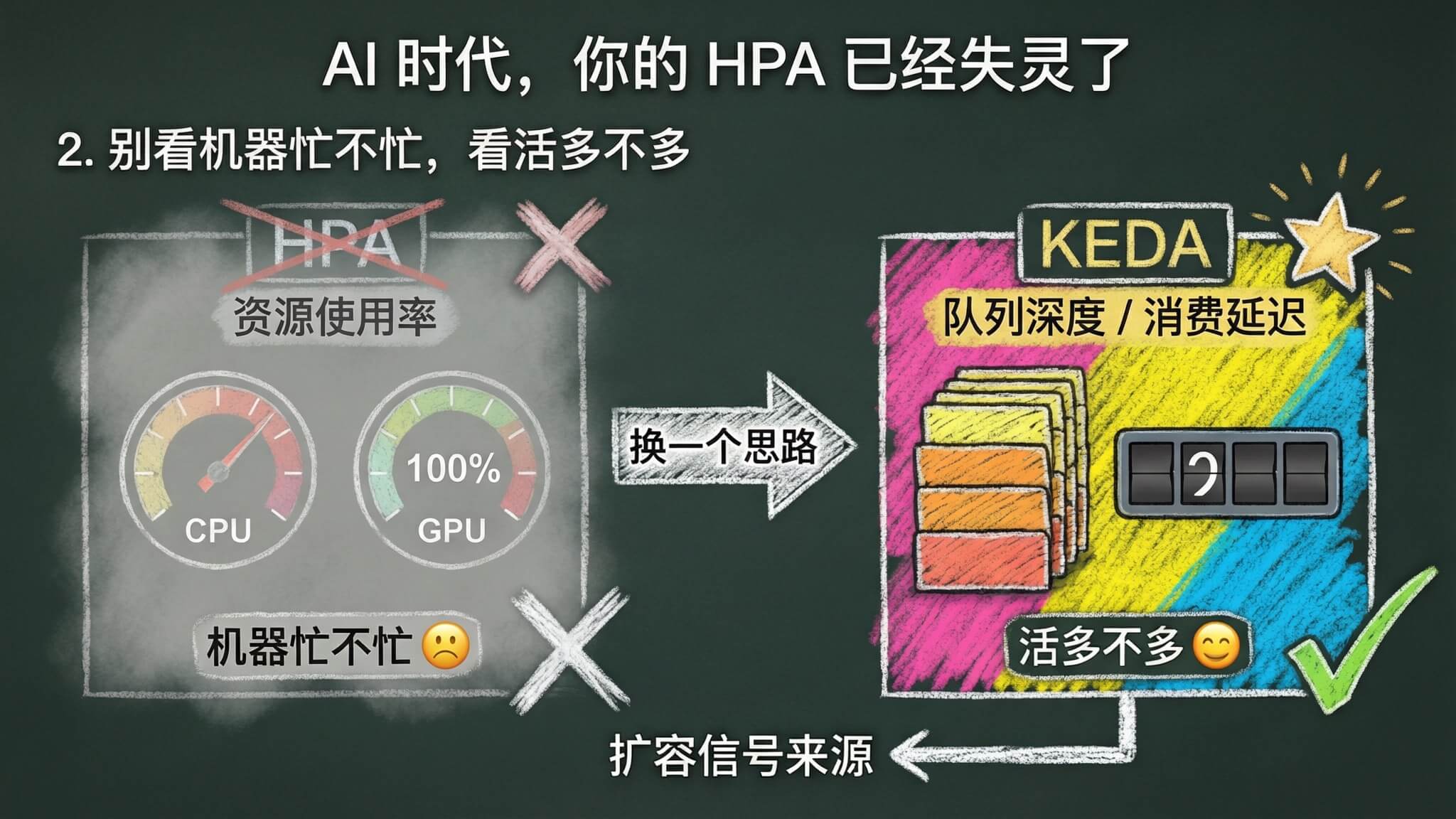
KEDA 干的就是这件事。
KEDA 全称 Kubernetes Event-driven Autoscaling,核心思路特别简单,根据外部事件源的状态来决定扩缩容,而不是看 Pod 的资源使用率。消息队列里有积压就扩,没消息就缩,就是这么直接。
用一张表对比一下 HPA 和 KEDA 的核心差异。
| 对比维度 | HPA | KEDA |
|---|---|---|
| 扩容信号来源 | Pod 资源使用率(CPU/内存/自定义指标) | 外部事件源(队列深度、消费延迟等) |
| 信号本质 | 机器侧,看「忙不忙」 | 需求侧,看「活多不多」 |
| Scale to Zero | 不支持,minReplicaCount 最低为 1 | 原生支持 |
| 外部指标接入复杂度 | 需要 Prometheus Adapter + ServiceMonitor + 自定义指标 + HPA 规则 | 一个 ScaledObject CRD 搞定 |
| 适合场景 | 传统 Web 服务,资源使用率与负载线性相关 | 异步处理,负载压力体现在队列积压 |
KEDA 支持 60 多种 Scaler,包括 Kafka、RabbitMQ、Redis、Prometheus、Cron 等,每个 Scaler 对接一种外部事件源,直接读取事件源的指标来决定扩缩容。
其中几个关键差异值得说一下。
可以缩到零。 没有请求的时候直接把 Pod 数量缩到 0,有请求来了再拉起来。对 GPU 这种昂贵资源来说,不用的时候就不占是最优的。
扩容信号直接来自需求侧。 不再绕一圈去猜 GPU 忙不忙,直接看队列深度、消费延迟这些业务强相关指标。
配置更简单。 用 HPA 接外部指标,你得部署 Prometheus Adapter、写 ServiceMonitor、配自定义指标、再写 HPA 规则,一整套流水线。KEDA 就一个 ScaledObject CRD,声明一下触发器类型和参数就搞定了。
下面用一个 demo 把整个流程跑一遍,让大家有一个大致的印象。
我们搞了一个 demo 项目,模拟一个典型的 AI 图片生成服务架构,演示完整的流程。 整体架构如下。
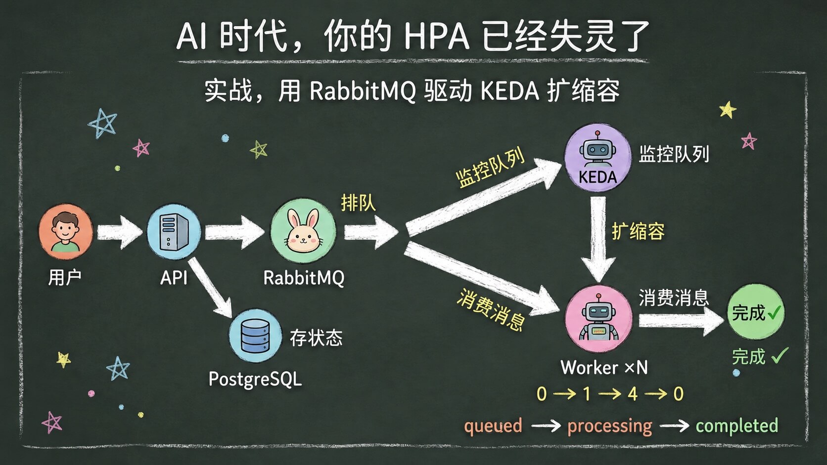
为什么选图片生成? 因为图片/视频生成是 KEDA 扩容最典型的 AI 场景。这类请求处理时间长,没法像 ChatGPT 那样实时返回,必须走异步架构。用户提交请求后拿到一个 task ID,过几秒再来查结果。这个架构和真实 Stable Diffusion API、ComfyUI 工作流、甚至 Sora 类视频生成服务的后端,逻辑是一样的。
为什么加了 DB? 因为真实的图片生成服务,用户提交请求后需要能查到任务状态,从 queued 到 processing 到 completed,这个生命周期需要持久化存储。MQ 只负责通知 Worker 有新任务,不负责存状态。
真实的 AI 推理当然不会用 sleep,这里用 sleep 只是为了模拟推理耗时,让你不用 GPU 也能跑通完整的 KEDA 扩缩容流程。架构、队列、扩缩容逻辑,跟生产环境一模一样。
代码和全部部署文件在 GitHub,keda-ai-queue-demo,下面逐个讲关键部分。
需要一个跑着 Kubernetes 的集群,并且装好 KEDA。
|
|
装完确认一下。
|
|
应该能看到 keda-operator 和 keda-operator-metrics-apiserver 两个 Pod 在运行。
克隆项目,直接 apply 即可,镜像已推送到 Docker Hub。
|
|
一行搞定部署,PostgreSQL、RabbitMQ、API、Worker、KEDA ScaledObject 全部拉起来。
|
|
确认 Pod 状态。
|
|
应该看到 PostgreSQL、RabbitMQ、API 三个 Pod 在运行,Worker 的 replicas 是 0,因为队列里还没消息,KEDA 不会给它扩容。
整个事件驱动扩缩容的配置就这一个 YAML。
|
|
逐个解释一下。
scaleTargetRef: worker,KEDA 只管 Worker 这个 Deployment,API 和 PostgreSQL 跟 KEDA 无关。
pollingInterval: 5,每 5 秒检查一次队列状态。AI 推理服务对响应时间敏感,轮询间隔可以设短一点,默认是 30 秒。
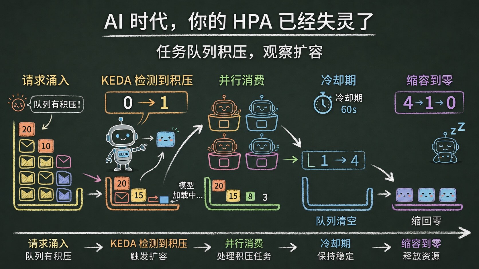
cooldownPeriod: 60,队列清空后 60 秒才缩容。demo 里设短一点方便观察,实际使用建议设 300 秒以上,避免模型反复加载。
minReplicaCount: 0,启用 scale to zero,没请求的时候不占资源。
mode: QueueLength,value: "5",每个 Pod 处理 5 条消息。队列里有 23 条消息,KEDA 就算出需要 ceil(23/5) = 5 个 Pod。
至于 KEDA 怎么连接 RabbitMQ,它通过
TriggerAuthentication从 Kubernetes Secret 里读取连接信息,不在 ScaledObject 里硬编码。具体可以看 demo 仓库的deploy/keda.yaml。
端口转发 API。
|
|
创建一批任务。
|
|
查一下任务状态。
|
|
状态流转是 queued -> processing -> completed,整个过程都有时间戳可以看。
打开另一个终端,观察 Worker Pod 数量变化。
|
|
你会看到 Worker 从 0 个 Pod 开始,KEDA 检测到队列有积压后,根据我们的配置把 Worker 扩到 4 个 Pod 并发消费。队列清空、冷却期结束后,Worker 又缩回 0。
KEDA 的操作日志也能看到完整过程。
|
|
|
|
0 -> 1 -> 4 -> 0,这就是 KEDA 事件驱动扩缩容的完整过程。
清理环境。
|
|
配置写起来简单,但真正使用起来还是有一些需要注意的地方:
冷启动问题。 从 0 扩到 N 意味着 Pod 要从零开始启动,包括加载模型到 GPU。大型图片生成模型的加载可能要 30 秒到 2 分钟,这段时间请求只能排队。如果业务对延迟敏感,最好把 minReplicaCount 设为 1,始终保留一个热 Pod。
cooldownPeriod 别设太短。 缩容后又来请求,重新扩容 + 模型加载,这个周期可能要一两分钟。频繁缩容再扩容的代价很大,Pod 反复启停,GPU 资源白白浪费在模型加载上。建议至少设 300 秒,让流量真正稳定下来再缩。
HPA 会被 KEDA 接管。 KEDA 会在底层创建一个 HPA,所以同一个 Deployment 不能再手动创建 HPA,会冲突。
轮询间隔要权衡。 pollingInterval 设得短,响应快,但对外部系统的 API 调用量也大。如果你有几百个 ScaledObject,每个 5 秒轮询一次,对消息队列的压力不小。根据实际场景在响应速度和资源消耗之间找个平衡点。
聊了这么多,最后收一下。
HPA 在 AI 推理场景下失灵,说到底是它的设计假设,资源使用率跟负载成正比,被 GPU 工作模式打破了。GPU 显存常驻、使用率脉冲、CPU/内存不跟负载走,HPA 看到的信号全是失真的。
KEDA 的思路是绕过资源指标,直接看需求侧的信号。消息队列里有多少消息在排队,就是最真实的扩容依据。
这个思路其实不只适用于 AI 推理,所有异步处理场景都有类似的扩缩容需求。只不过 AI 推理把这个问题放大了,因为 GPU 太贵了,扩错一台就是真金白银的浪费。
几个要点:
如果你的 AI 推理服务还在用 HPA,建议重新审视一下扩容策略,可能它已经在「失灵」了,只是你还没注意到。